- 您现在的位置:买卖IC网 > Sheet目录473 > MAX2538ETI+T (Maxim Integrated)IC LNA/MIXER CELL/PCS/GPS 28TQFN
�� �
�
�Quadruple-Mode� PCS/Cellular/GPS� LNA/Mixers�
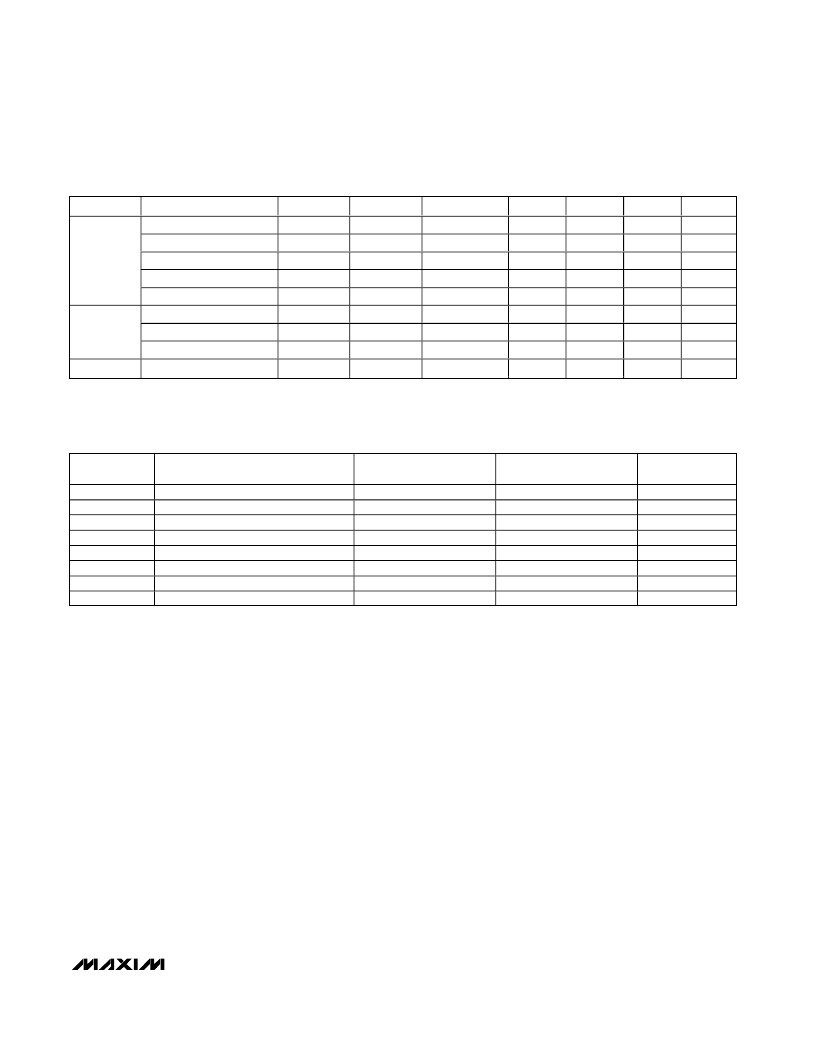
�Table� 2.� Modes� of� Operation�
�BAND�
�Cellular�
�PCS�
�GPS*�
�OPERATION� MODE�
�HGHL�
�HGLL�
�MG�
�LG�
�ULG�
�HGHL�
�LG�
�ULG�
�GPS�
�LNA�
�HGHL�
�HGLL�
�MG�
�LG�
�LG�
�HGHL�
�LG�
�LG�
�GPS�
�MIXER�
�HL�
�LL�
�HL�
�LL�
�LG�
�HL�
�LL�
�LG�
�GPS�
�IF� PORT�
�IF0� or� IF1�
�IF0� or� IF1�
�IF0� or� IF1�
�IF0� or� IF1�
�IF0� or� IF1�
�IF0� or� IF1�
�IF0� or� IF1�
�IF0� or� IF1�
�GIF�
�G2�
�0�
�0�
�0�
�1�
�1�
�0�
�1�
�1�
�0�
�G1�
�0�
�0�
�1�
�1�
�0�
�0�
�1�
�0�
�0�
�MODE�
�1�
�0�
�X�
�X�
�X�
�1�
�X�
�X�
�0�
�BAND�
�0�
�0�
�0�
�0�
�0�
�1�
�1�
�1�
�1�
�*� MAX2530/MAX2531/MAX2537/MAX2538� only.�
�X� =� Don’t� care.�
�Table� 3.� LO� Frequency� Plan�
�PART�
�MAX2351�
�MAX2354�
�MAX2358�
�MAX2359�
�MAX2530�
�MAX2531�
�MAX2537�
�MAX2538�
�VCO� FREQUENCY�
�Cell� Band� VCO�
�Cell� Band� VCO�
�PCS� Band� VCO�
�PCS� Band� VCO�
�Cell� and� PCS� Dual-Band� VCO�
�Cell� Band� VCO�
�PCS� Band� VCO�
�PCS� Band� VCO�
�CELLULAR� LO�
�FREQUENCY�
�f� VCO�
�f� VCO�
�0.5� x� f� VCO�
�—�
�f� VCO�
�f� VCO�
�0.5� x� f� VCO�
�0.5� x� f� VCO�
�PCS� LO� FREQUENCY�
�2� x� f� VCO�
�—�
�f� VCO�
�f� VCO�
�f� VCO�
�2� x� f� VCO�
�—�
�f� VCO�
�GPS� LO�
�FREQUENCY�
�—�
�—�
�—�
�—�
�(2/3)� f� VCO�
�(4/3)� f� VCO�
�(2/3)� f� VCO�
�(2/3)� f� VCO�
�GPS� Interstage�
�The� GPS� LNA� and� mixer� include� on-chip� resonant� tanks�
�that� can� be� used� instead� of� a� saw� filter� for� image� sup-�
�pression.� These� tanks� are� coupled� by� an� external� L-C�
�network� between� pins� 8� and� 10� as� shown� in� the� Typical�
�Application� Circuit� .�
�Layout� Considerations�
�Keep� RF� signal� lines� as� short� as� possible� to� minimize�
�losses� and� radiation.� Use� controlled� impedance� on� all�
�high-frequency� traces.� Use� high-Q� (>40)� components�
�for� the� LNA� input-matching� circuit� to� achieve� the� lowest�
�possible� noise� figure.� At� the� mixer� outputs,� keep� the�
�differential� signal� lines� together� and� of� equal� length� to�
�ensure� signal� balance.� For� proper� operation,� solder� the�
�exposed� paddle� evenly� to� the� ground� plane.� Use� abun-�
�dant� ground� vias� between� RF� traces� to� minimize� unde-�
�sired� coupling.�
�______________________________________________________________________________________�
�11�
�发布紧急采购,3分钟左右您将得到回复。
相关PDF资料
MAX2608EVKIT
EVAL KIT
MAX2611EUS+T
IC AMP LOW NOISE SOT143-4
MAX2616EVKIT#
EVAL KIT MAX2616
MAX2620EVKIT
EVAL KIT MAX2620
MAX2623EVKIT
EVAL KIT
MAX2632EUK+T
IC AMP 3V VHF/MICROWAVE SOT23-5
MAX2634EVKIT+
KIT EVAL FOR MAX2634 AUTO AMP
MAX2641EVKIT
EVAL KIT MAX2640, MAX2641
相关代理商/技术参数
MAX2538ETI-B6A
功能描述:射频混合器 RoHS:否 制造商:NXP Semiconductors 频率范围: 转换损失——最大: 工作电源电压:6 V 最大工作温度:+ 85 C 最小工作温度:- 40 C 安装风格:Through Hole 封装 / 箱体:PDIP-8 封装:Tube
MAX2538ETI-G104
制造商:Rochester Electronics LLC 功能描述: 制造商:Maxim Integrated Products 功能描述:
MAX2538ETI-T
功能描述:射频混合器 Quad-Mode PCS/Cell GPS LNA/Mixers RoHS:否 制造商:NXP Semiconductors 频率范围: 转换损失——最大: 工作电源电压:6 V 最大工作温度:+ 85 C 最小工作温度:- 40 C 安装风格:Through Hole 封装 / 箱体:PDIP-8 封装:Tube
MAX2538ETI-TB6A
功能描述:射频混合器
RoHS:否 制造商:NXP Semiconductors 频率范围: 转换损失——最大: 工作电源电压:6 V 最大工作温度:+ 85 C 最小工作温度:- 40 C 安装风格:Through Hole 封装 / 箱体:PDIP-8 封装:Tube
MAX2538ETI-TG097
制造商:Rochester Electronics LLC 功能描述: 制造商:Maxim Integrated Products 功能描述:
MAX2538EVKIT
功能描述:射频开发工具 MAX2538 Eval Kit RoHS:否 制造商:Taiyo Yuden 产品:Wireless Modules 类型:Wireless Audio 工具用于评估:WYSAAVDX7 频率: 工作电源电压:3.4 V to 5.5 V
MAX2539EGI
功能描述:射频放大器
RoHS:否 制造商:Skyworks Solutions, Inc. 类型:Low Noise Amplifier 工作频率:2.3 GHz to 2.8 GHz P1dB:18.5 dBm 输出截获点:37.5 dBm 功率增益类型:32 dB 噪声系数:0.85 dB 工作电源电压:5 V 电源电流:125 mA 测试频率:2.6 GHz 最大工作温度:+ 85 C 安装风格:SMD/SMT 封装 / 箱体:QFN-16 封装:Reel
MAX2539EGI-T
功能描述:射频放大器
RoHS:否 制造商:Skyworks Solutions, Inc. 类型:Low Noise Amplifier 工作频率:2.3 GHz to 2.8 GHz P1dB:18.5 dBm 输出截获点:37.5 dBm 功率增益类型:32 dB 噪声系数:0.85 dB 工作电源电压:5 V 电源电流:125 mA 测试频率:2.6 GHz 最大工作温度:+ 85 C 安装风格:SMD/SMT 封装 / 箱体:QFN-16 封装:Reel