- 您现在的位置:买卖IC网 > Sheet目录473 > MAX2538ETI+T (Maxim Integrated)IC LNA/MIXER CELL/PCS/GPS 28TQFN
Quadruple-Mode PCS/Cellular/GPS LNA/Mixers
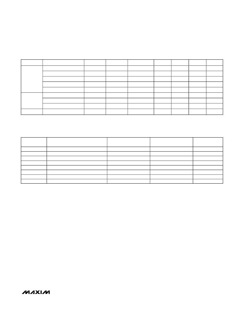
Table 2. Modes of Operation
BAND
Cellular
PCS
GPS*
OPERATION MODE
HGHL
HGLL
MG
LG
ULG
HGHL
LG
ULG
GPS
LNA
HGHL
HGLL
MG
LG
LG
HGHL
LG
LG
GPS
MIXER
HL
LL
HL
LL
LG
HL
LL
LG
GPS
IF PORT
IF0 or IF1
IF0 or IF1
IF0 or IF1
IF0 or IF1
IF0 or IF1
IF0 or IF1
IF0 or IF1
IF0 or IF1
GIF
G2
0
0
0
1
1
0
1
1
0
G1
0
0
1
1
0
0
1
0
0
MODE
1
0
X
X
X
1
X
X
0
BAND
0
0
0
0
0
1
1
1
1
* MAX2530/MAX2531/MAX2537/MAX2538 only.
X = Don’t care.
Table 3. LO Frequency Plan
PART
MAX2351
MAX2354
MAX2358
MAX2359
MAX2530
MAX2531
MAX2537
MAX2538
VCO FREQUENCY
Cell Band VCO
Cell Band VCO
PCS Band VCO
PCS Band VCO
Cell and PCS Dual-Band VCO
Cell Band VCO
PCS Band VCO
PCS Band VCO
CELLULAR LO
FREQUENCY
f VCO
f VCO
0.5 x f VCO
—
f VCO
f VCO
0.5 x f VCO
0.5 x f VCO
PCS LO FREQUENCY
2 x f VCO
—
f VCO
f VCO
f VCO
2 x f VCO
—
f VCO
GPS LO
FREQUENCY
—
—
—
—
(2/3) f VCO
(4/3) f VCO
(2/3) f VCO
(2/3) f VCO
GPS Interstage
The GPS LNA and mixer include on-chip resonant tanks
that can be used instead of a saw filter for image sup-
pression. These tanks are coupled by an external L-C
network between pins 8 and 10 as shown in the Typical
Application Circuit .
Layout Considerations
Keep RF signal lines as short as possible to minimize
losses and radiation. Use controlled impedance on all
high-frequency traces. Use high-Q (>40) components
for the LNA input-matching circuit to achieve the lowest
possible noise figure. At the mixer outputs, keep the
differential signal lines together and of equal length to
ensure signal balance. For proper operation, solder the
exposed paddle evenly to the ground plane. Use abun-
dant ground vias between RF traces to minimize unde-
sired coupling.
______________________________________________________________________________________
11
发布紧急采购,3分钟左右您将得到回复。
相关PDF资料
MAX2608EVKIT
EVAL KIT
MAX2611EUS+T
IC AMP LOW NOISE SOT143-4
MAX2616EVKIT#
EVAL KIT MAX2616
MAX2620EVKIT
EVAL KIT MAX2620
MAX2623EVKIT
EVAL KIT
MAX2632EUK+T
IC AMP 3V VHF/MICROWAVE SOT23-5
MAX2634EVKIT+
KIT EVAL FOR MAX2634 AUTO AMP
MAX2641EVKIT
EVAL KIT MAX2640, MAX2641
相关代理商/技术参数
MAX2538ETI-B6A
功能描述:射频混合器 RoHS:否 制造商:NXP Semiconductors 频率范围: 转换损失——最大: 工作电源电压:6 V 最大工作温度:+ 85 C 最小工作温度:- 40 C 安装风格:Through Hole 封装 / 箱体:PDIP-8 封装:Tube
MAX2538ETI-G104
制造商:Rochester Electronics LLC 功能描述: 制造商:Maxim Integrated Products 功能描述:
MAX2538ETI-T
功能描述:射频混合器 Quad-Mode PCS/Cell GPS LNA/Mixers RoHS:否 制造商:NXP Semiconductors 频率范围: 转换损失——最大: 工作电源电压:6 V 最大工作温度:+ 85 C 最小工作温度:- 40 C 安装风格:Through Hole 封装 / 箱体:PDIP-8 封装:Tube
MAX2538ETI-TB6A
功能描述:射频混合器
RoHS:否 制造商:NXP Semiconductors 频率范围: 转换损失——最大: 工作电源电压:6 V 最大工作温度:+ 85 C 最小工作温度:- 40 C 安装风格:Through Hole 封装 / 箱体:PDIP-8 封装:Tube
MAX2538ETI-TG097
制造商:Rochester Electronics LLC 功能描述: 制造商:Maxim Integrated Products 功能描述:
MAX2538EVKIT
功能描述:射频开发工具 MAX2538 Eval Kit RoHS:否 制造商:Taiyo Yuden 产品:Wireless Modules 类型:Wireless Audio 工具用于评估:WYSAAVDX7 频率: 工作电源电压:3.4 V to 5.5 V
MAX2539EGI
功能描述:射频放大器
RoHS:否 制造商:Skyworks Solutions, Inc. 类型:Low Noise Amplifier 工作频率:2.3 GHz to 2.8 GHz P1dB:18.5 dBm 输出截获点:37.5 dBm 功率增益类型:32 dB 噪声系数:0.85 dB 工作电源电压:5 V 电源电流:125 mA 测试频率:2.6 GHz 最大工作温度:+ 85 C 安装风格:SMD/SMT 封装 / 箱体:QFN-16 封装:Reel
MAX2539EGI-T
功能描述:射频放大器
RoHS:否 制造商:Skyworks Solutions, Inc. 类型:Low Noise Amplifier 工作频率:2.3 GHz to 2.8 GHz P1dB:18.5 dBm 输出截获点:37.5 dBm 功率增益类型:32 dB 噪声系数:0.85 dB 工作电源电压:5 V 电源电流:125 mA 测试频率:2.6 GHz 最大工作温度:+ 85 C 安装风格:SMD/SMT 封装 / 箱体:QFN-16 封装:Reel
